Paisley’s Perch aka Modern Cat Furniture

If you didn’t know, I’m a cat person and we just got a new Oriental Longhair kitten. I’m also a dog person and we have a beautiful long hair mini Dachshund. The two of them are getting along fine but the kitten needed a place “above it all” to see the world and escape the little dog. This is my second foray into making some sort of cat furniture, here’s a LINK to the blog of a more complicated piece I made for Khali who sadly passed away last year.

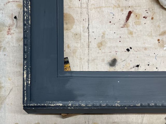
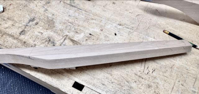
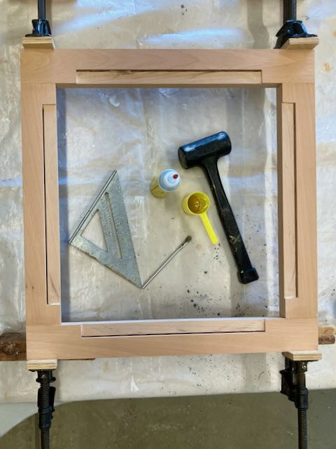
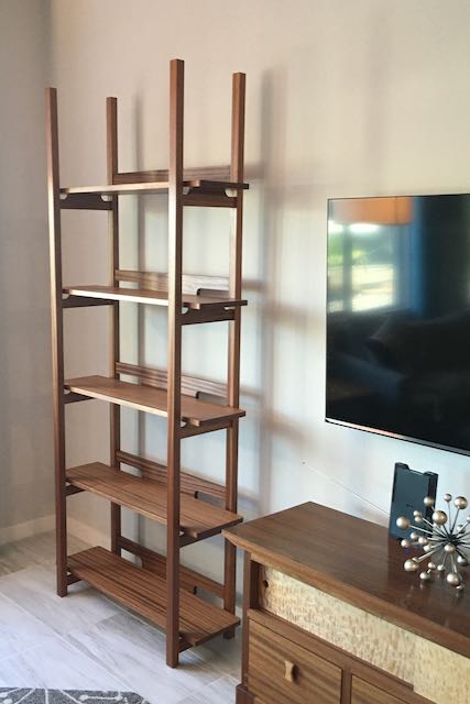
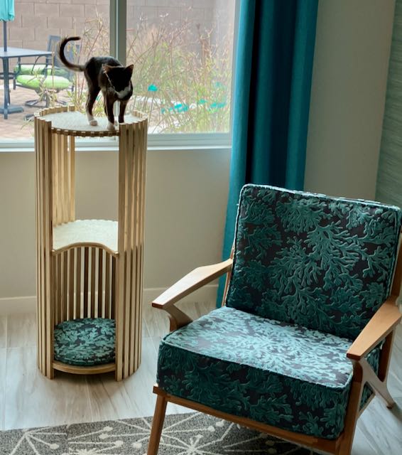
Typical cat furniture is usually made of MDF and carpet, fairly heavy, and maybe kind of cute but in my experience it loses its appeal and after some use the carpet starts to look pretty ragged. Okay for a back room but not something you’d want to display in your living room. After looking on Pinterest for ideas we found that the really attractive pieces were from other countries or super expensive but they gave us inspiration. Diane noted that most of our furniture is square or rectangle so a circular pieces would add some variety. In the picture above is what we came up with after she made some mockups from foam core and tape. My first choice was clear coat Baltic Birch which had 2 disadvantages; cost was the first one and the benefit of the clear coat means the plies need to be exposed in any joinery or else glue won’t stick to it. Decided to try Home Depot’s Radiata Pine panels and it worked out quite nicely at an affordable price.

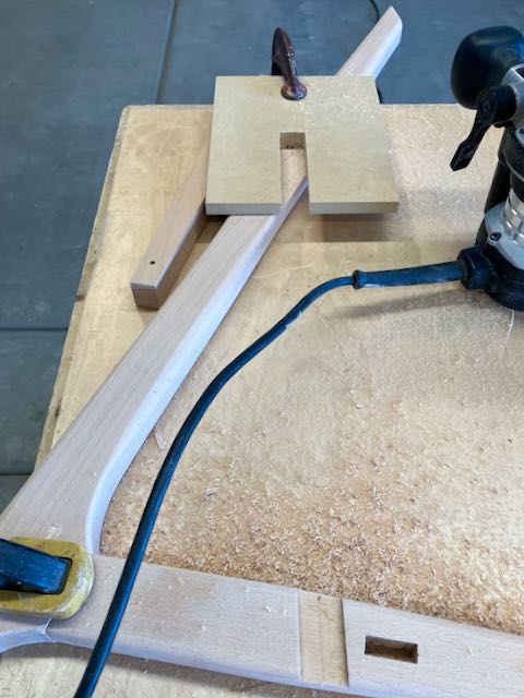
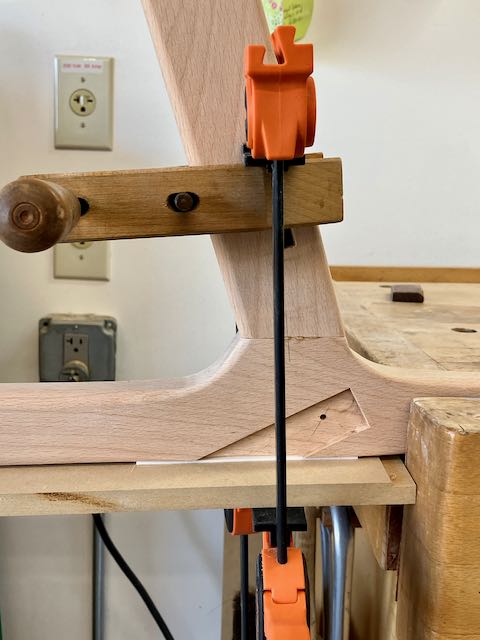
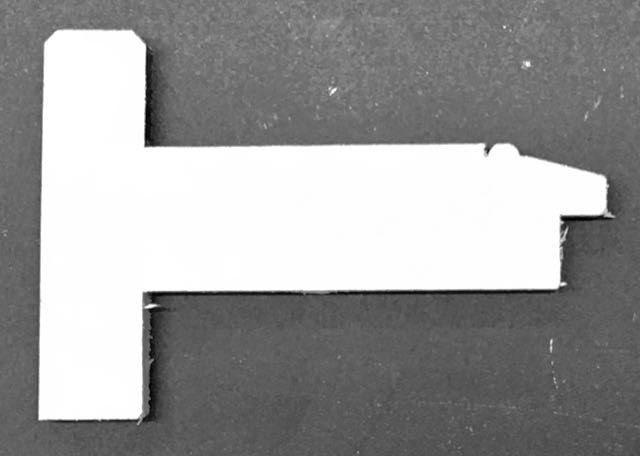
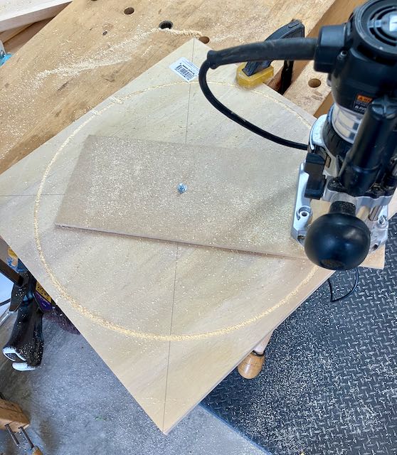
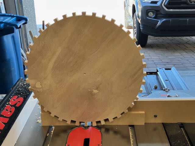
The first step was making the three circles, I knew the challenge would be cutting the dados in them but figured I’d deal with that later! I went about this in a different way, the first step was to make a compass arm from 1/4″ MDF and attach my router to it to make the circles. I wanted this smoother than a bandsawn piece and have compression cut pattern bit from Woodpeckers which makes a super smooth cut even on plywood. The bearing is at the bottom so the first step was making a pattern from MDF. Next I located the center of the plywood, attached the router compass and used a 3/8″ bit to cut a shallow dado. This dado was my guide to cut the circle on the bandsaw. After that I clamped the template to the plywood and used the pattern bit to cut a smooth circle.

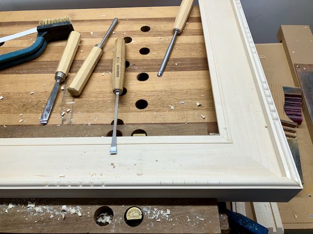
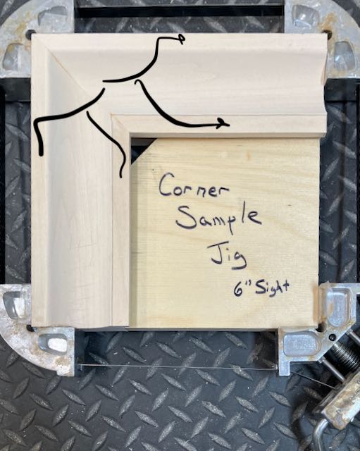
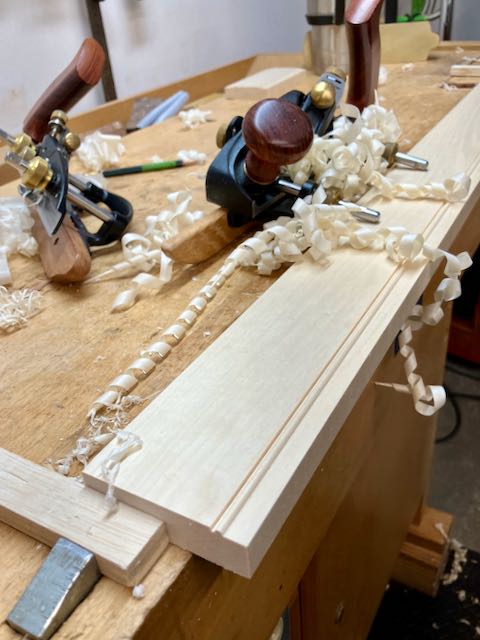
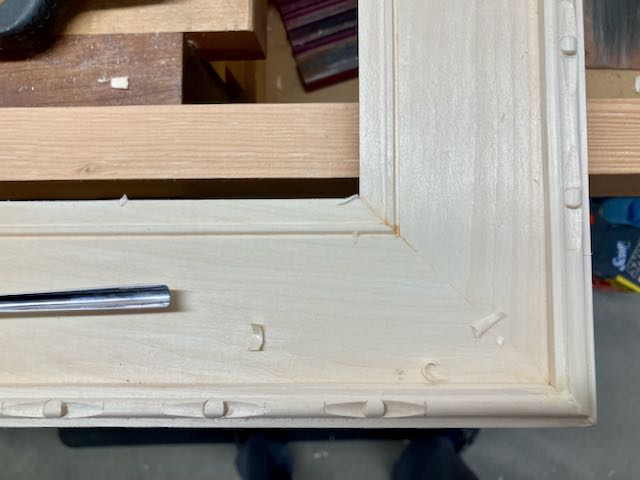
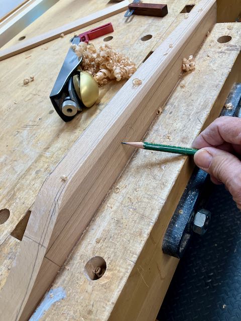
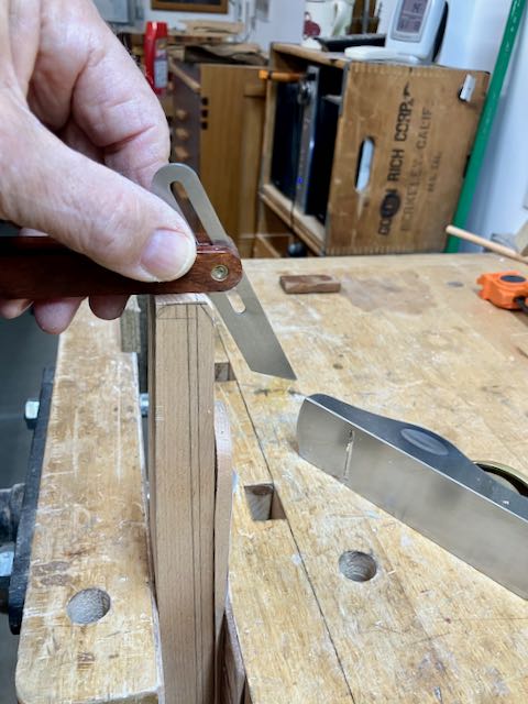
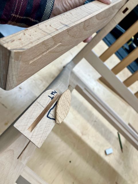
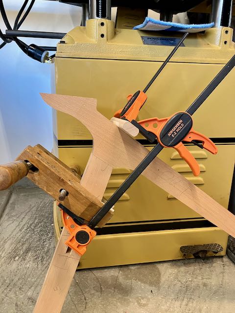
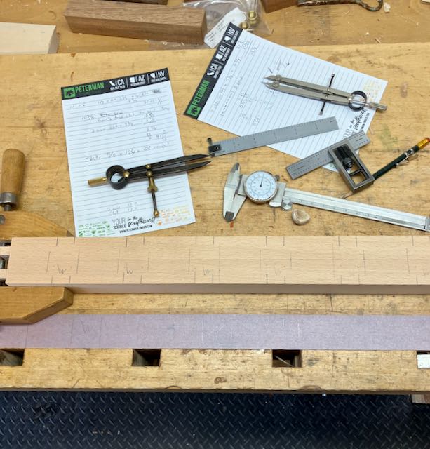
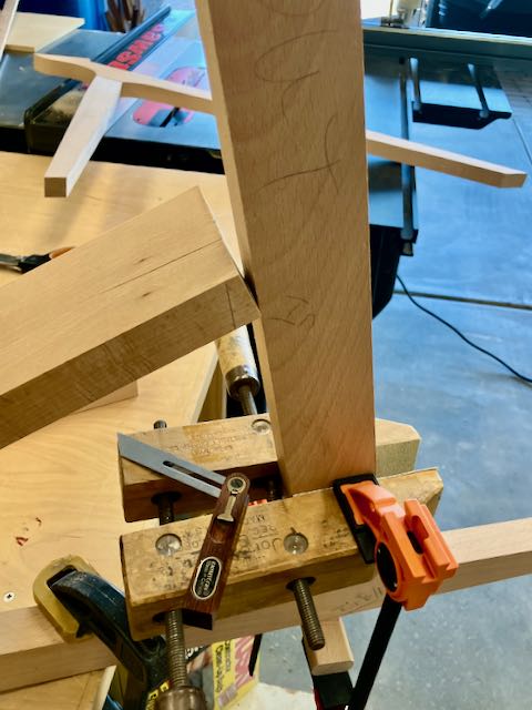
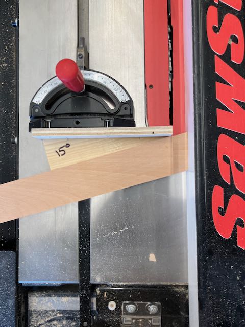
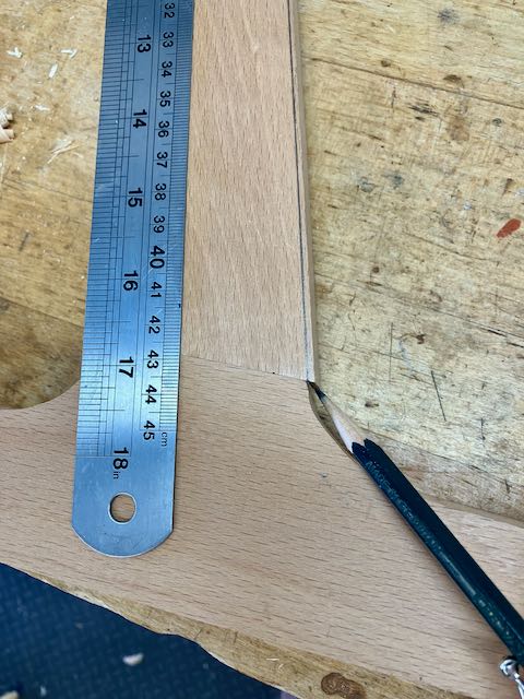
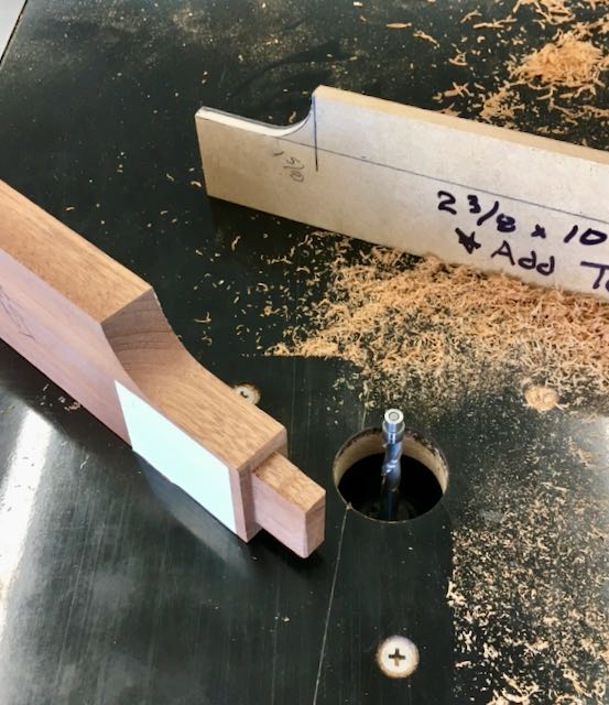
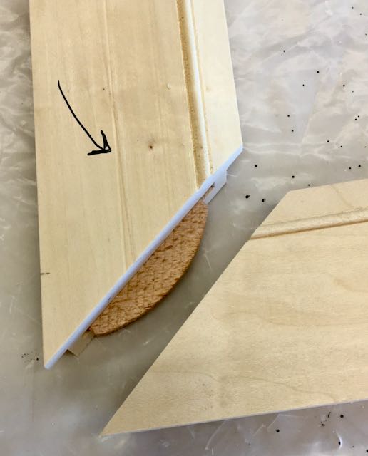
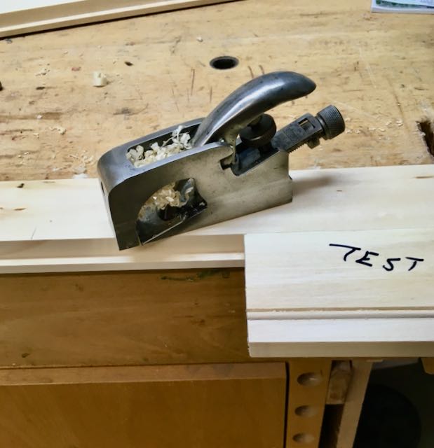
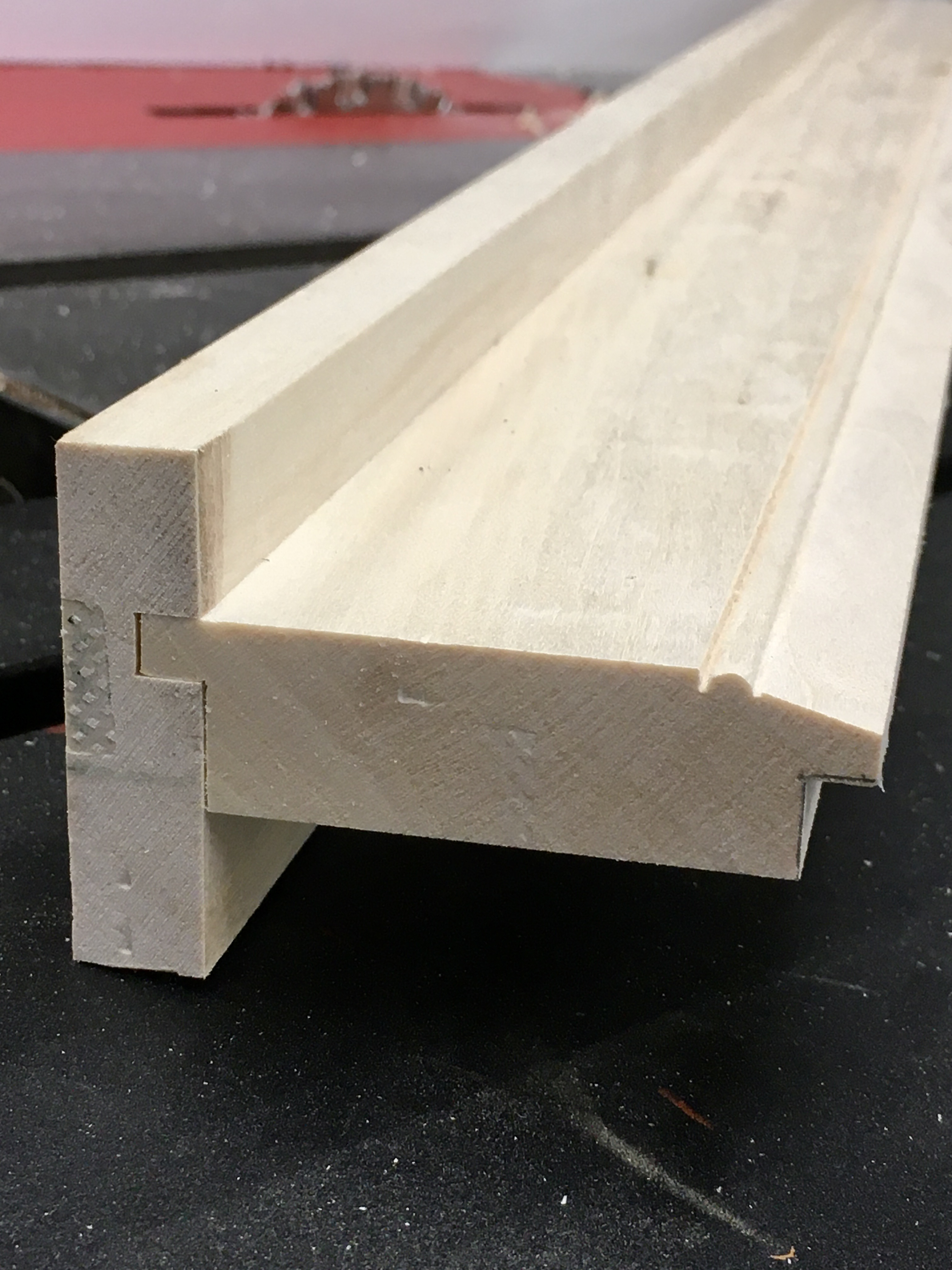
The next challenge was cutting 3/4″ equally spaced dados around the perimeter of the circle. I decided to take one quarter of the circle and use dividers to step off even divisions; that’s similar to the technique used to lay out dovetails. I learned though that where the divider mark is made in relation to the distance from the edge changes the location of it! Now, how to cut them — here’s some photos and I’ll explain the process. Here’s where CNC would simplify it but take the human out of the equation which is something that goes against my philosophy. My goal through out my teaching career was to have my students figure out their projects using their own resources at a minimum outlay for tools. Of course, it they went into it as a career they’d need to use the most efficient and quick way to manufacture their products.

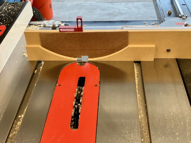
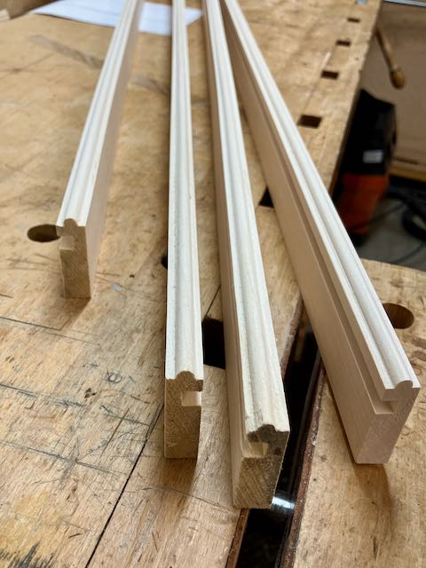
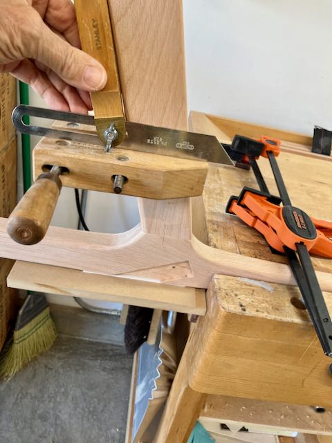
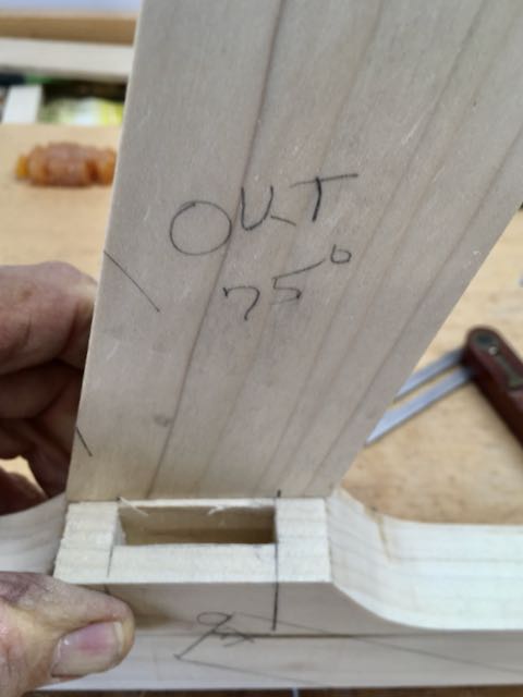
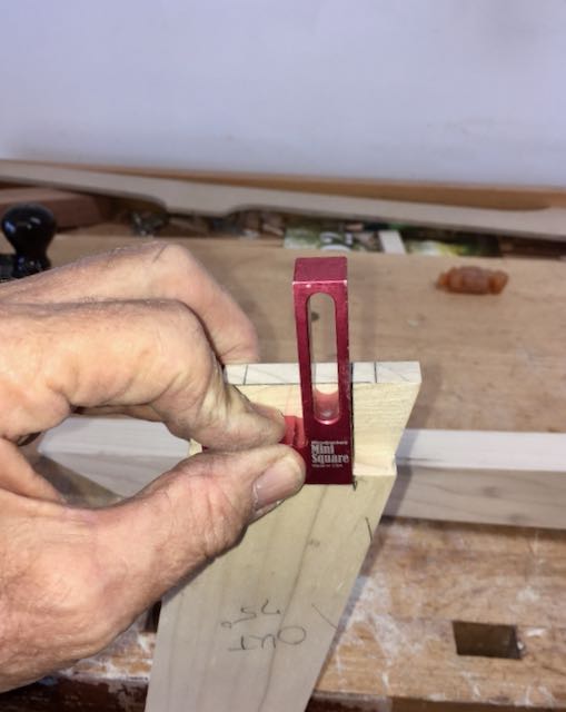
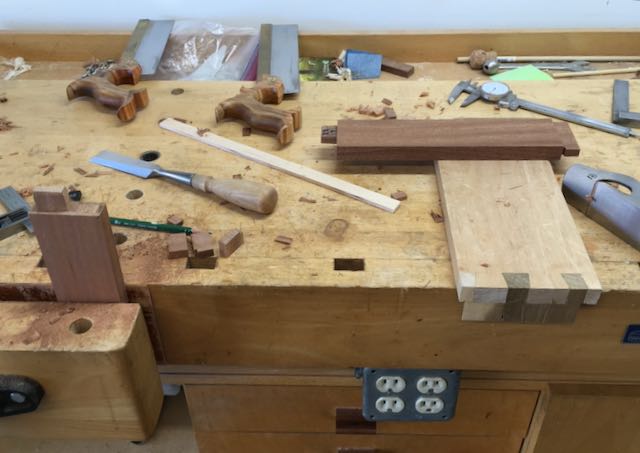
Problems: First of all, I made the jig to line up to the center of the dado but discovered that no matter how carefully I “eyeballed” the line, it wasn’t always exact. There is a section on each disc that needed to be either cut out for cat access or, in the case of the bottom one, be left without any dados. Add to that they needed to be aligned so the cat access hole was in the proper location on the middle and top disc. My solution was to cut only 1 dado in the remaining two discs. Then I marked off where the access was for each and labeled them Top, Middle, and Bottom. That initial dado was used to align them and they were screwed together through the center hole. I carefully penciled in one side of each needed dado and made another mark on the throat plate of the saw to align it with and proceeded to cut the remaining dados. Note: This is rather lengthy and maybe confusing so if you decide to make something similar and have questions please don’t hesitate to send me a message. I use many of my blogs as an on-line journal to remind me how I did something in the past.

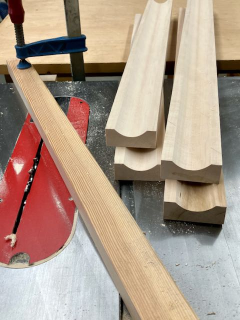
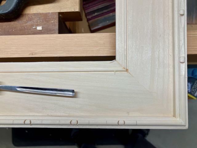
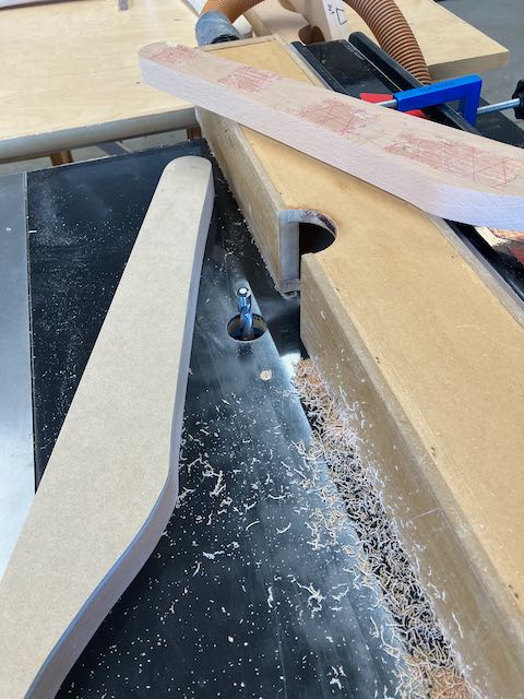
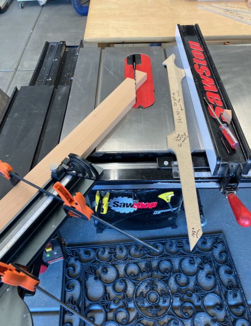
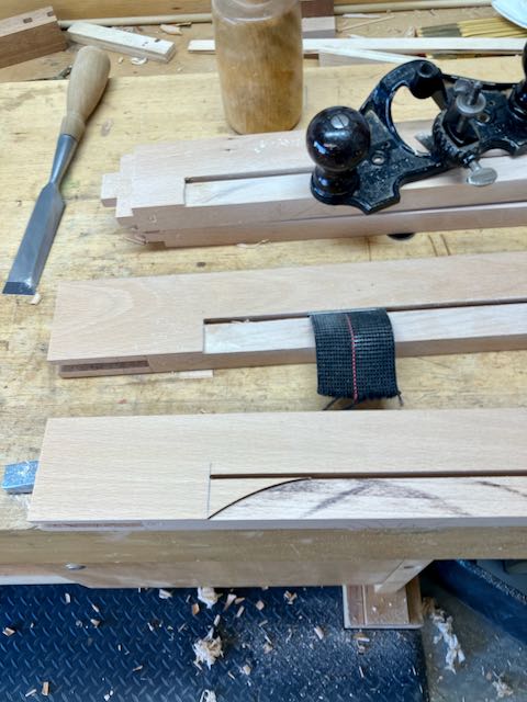
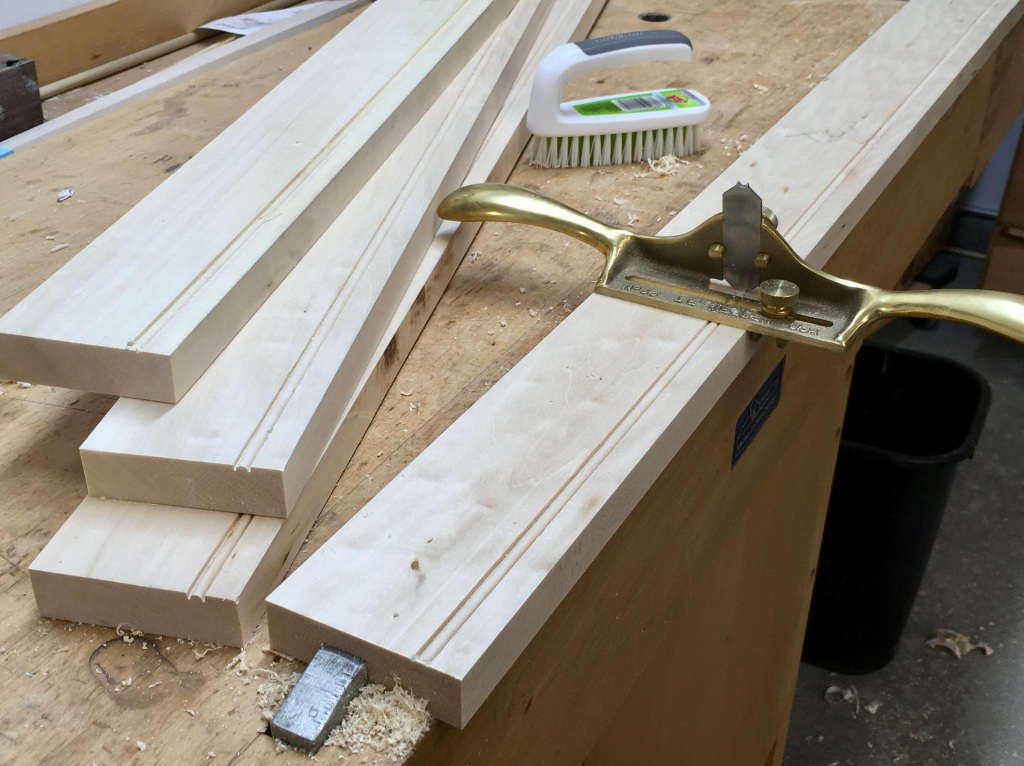
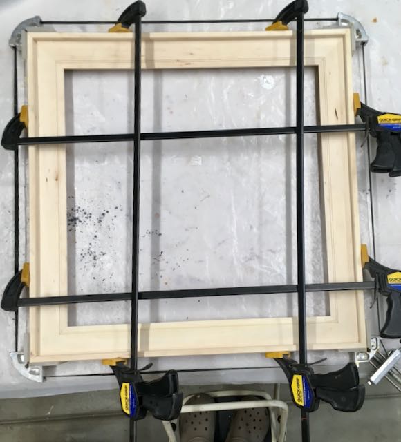
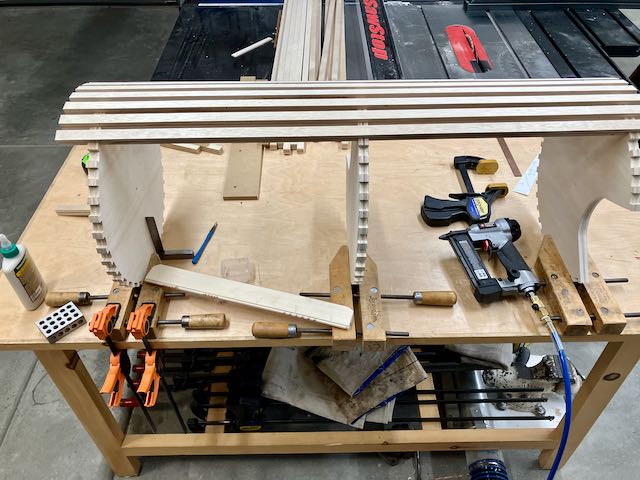
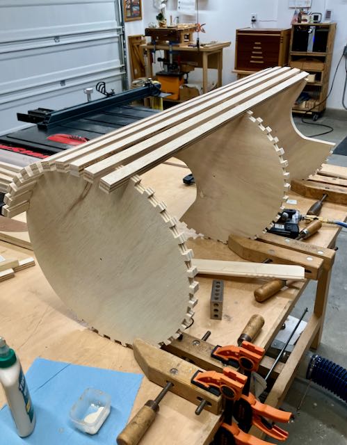
Assembly followed and the first step there was to cut the slats, the full length ones are about 39″ and made from the 3/4″ plywood. Once the fence was set to the width they were all cut on the tablesaw. I used a 2″ spacer for the bottom one, then another spacer for the distance between the discs. The slats are glued into the dado and held in place with 2, 23 gauge pins at each joint. Each disc was held on my assembly table with a parallel clamp which helped align them. I started with the dado marked bottom, middle, and top and worked my way around.

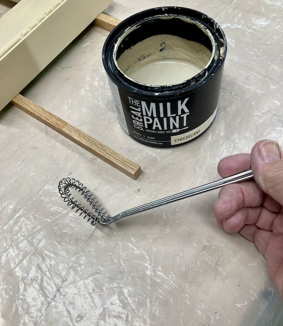
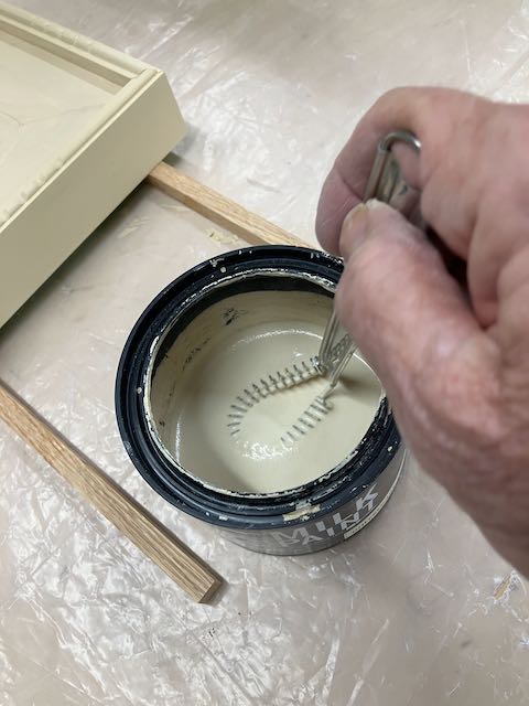
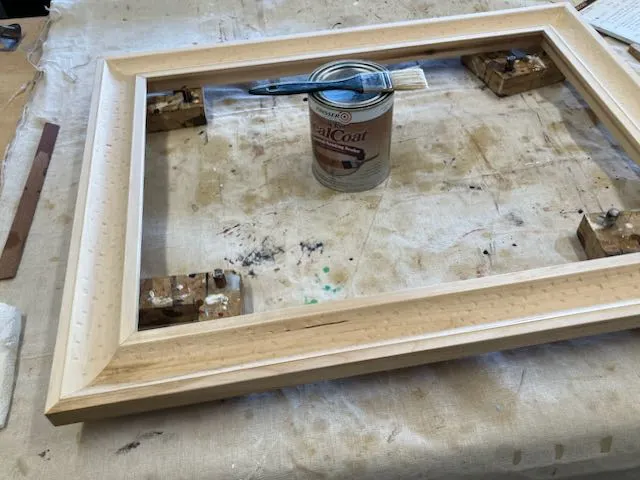
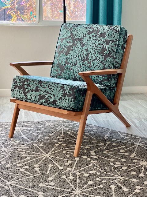
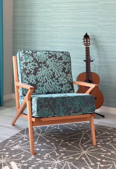
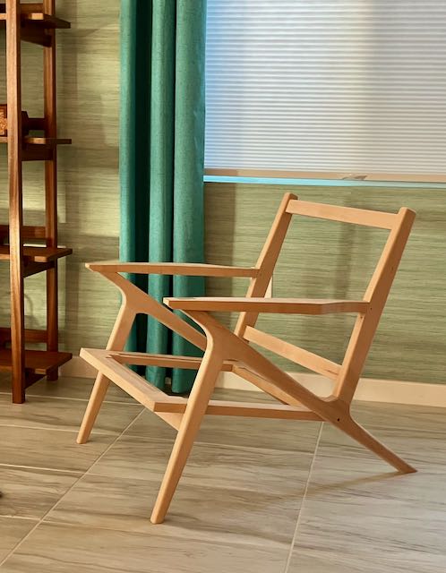
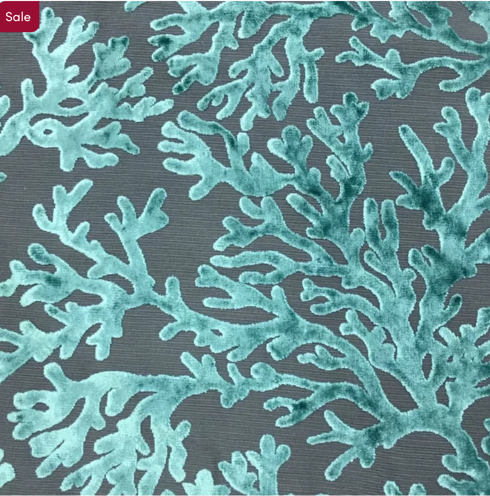
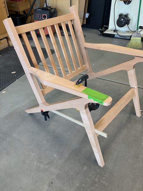
Once everything was dry the slats were lightly sanded and a coat of OSMO 3043 applied to provide some protection. We had material left over from my interpretation of the Z-Chair so Diane made a cushion to match it. We accomplished our goal which was to create a stylish piece of cat furniture that compliments our decor. Most important of all it’s been:

Paisley Approved !!
Posted in Uncategorized | Tagged , , , , , , , , , , , , | Leave a comment

Frame #249 Real Milk Paint and their Chippy Product

This is the second time I’ve used milk paint from Real Milk Paint Company to finish a frame. I’ve added a link to my blog about that frame. The design and construction of both frames is similar, the only difference is in the carving on the outer band and the color of the paint. You can see the first blog here where I went into more detail about making the frame. I’ve had a number of comments asking about the technique I used to finish it and this blog is about that.

After assembly, the first step was to apply the base coat of Cheesecake from RMP. It has a warmth that appealed to me. On the first frame I used their Black Iron which, as the name implies; is a deep black. For this frame I wanted to experiment with creating a custom color. The Real Milk Paint Co. has a color chart showing how blending their Soft White with any other color will customize that color. I used 1 part of the Soft White to 9 parts of the Black Iron. I discovered that using and mixing small quantities of the milk paint with their marble techniques left too much of the paint powder in the can. Lee Valley hardware has this small min whisk which I found to work well after bending the whisk section upwards which lets you get to the bottom of the can. I used the marble technique too. These pictures show the procedure:

The painting this frame was created for is titled Shop Girl, it’s oil on stretched canvas, measures 24″ square, and was painted by my wife Diane Eugster. After the base coat was applied it was scuff sanded with 320 paper. No sanding between the top coats as that would probably remove some of the Chippy material. I did lightly scuff sand the final top coat with a white, nylon scrubby before rubbing on two coats of the OSMO Polyx 3043 satin. My goal was to expose enough of the top coat to replicate some aging but not so much that it’d look like a beat up old frame. The base coat compliments that light vertical detail near the center of the painting while the final coat mimics the shop girls skirt. That’s what makes a frame truly custom.

Since it’s difficult to show the entire frame in a photograph I made this short video “tour” of how the entire frame looks, it’s on my YouTube Channel.

Posted in Uncategorized | Tagged , , , , , , , , , | Leave a comment

Silver Leaf and Textured Cove

The title of this 18″x24″ oil on stretched canvas is The Parisian, painted by Diane Eugster. Since posting this frame and painting I’ve received a number of comments about how the frame was made and how long it took. It’s interesting to me how often people ask how long a project takes to complete so this was one of those occasions where I kept track of my actual work time. This particular frame took approximately 10 hours of actual work time. To be honest, I’m not that concerned about how long projects take; my motivation is more about meeting the challenge and accomplishment a goal. Many furniture projects take 50-80+ hours but my adage is that time is care, not the familiar one of time being money.

I used 5/4, rough Basswood stock for this frame and was able to mill that down to a finished thickness of 1 1/8″. These pieces were 2 7/8″ wide and left long to allow for the miters. The first step was to cut a cove in each piece using the tablesaw, followed by lots of sanding to remove marks left during the cove cutting process. To cut those coves you need to clamp a long straight edge at an angle behind the blade then cut the cove by raising the blade in small increments until your desired depth is achieved. I won’t go into the details of how you set this up but there are many sources on the internet — be warned; please use a credible source!

After cutting the rabbet I also cut a slight, 30° chamfer on the outside, back edge of the molding. This makes the frame appear to float away from the wall. A skew rabbet plane was used to form a shallow, flat area on both sides of the cove, I’ve marked those areas in the picture. These outline the cove and give a definite edge to separate the black Japan paint from the cove. Makes it easier to tape too! Lastly, the pieces were mitered, biscuit slots cut, and then glued/clamped overnight. I usually make a sample corner for new designs and you can see the details of the frame in it.

After assembly it was time to start texturing the coved area. I experimented with different gouges and decided to use a #7 sweep that was 10mm wide. This particular gouge had a long bend to it which made it easier to get to all areas of the cove. Do you realize how difficult it is to develop a truly random pattern? After doing a section I’d step back and look at it, then try to decide if there was a pattern or if there were too many or not enough cuts, do I need more, should there be less, etc. Finally I decided to listen to my daughters favorite phrase: “it is what it is” and let it be. The entire frame was checked over, sanded as needed and then I brush on a coat of Zinsser shellac seal coat to all surfaces which is lightly sanded with 400 grit paper before the final finish. 

The finishing process was a succession of first taping off the cove to apply the Japan Black to the edges. When that was dry, the edges were taped off to apply the gray sealer/burnisher. That tape was removed and replaced with the yellow 3M tape prior to applying the slow set size and the laying metal, silver leaf. I’ve found that the yellow tape leaves a cleaner edge since it’s thinner. When I lay composition leaf I use my fingers and cut it to size with a single edge razor blade. I’ve found that if you press firmly down on 6 or so leaves and cut them on a piece of plywood they cut cleanly. This is much, much easier than handling them with a gilders knife on a pad. With this cove I was actually able to pick up the leaf and paper at the same time and use similar to how patent leaf is applied. I’d do one side of the cove first and then come back to do the opposite side.

After the slow set size was completely dry the leaf was carefully burnished with 4/0, oil free Liberon steel wool to tone down the shine of the composition leaf. This was followed by a few coats of Platinum Blonde shellac applied with an air brush. The final step for my finish is to use a white nylon scrubby and Liberon neutral paste wax to tone down the gloss of the shellac. Here’s a final picture is of a corner detail — I believe it complements the picture nicely!

Textured, silver leafed frame — Corner Detail
Posted in Uncategorized | Tagged , , , , , , , , , , , , , | Leave a comment

Real Milk Paint for Frame #245

My wife and I were visiting an artist friend of hers and she showed us an antique picture frame she had. It had a lot of patina (another word for beat up) where gesso had broken off, paint was worn off down to the wood, etc. Well, Diane said she really liked that look and; as usual for me, I said “I can probably do that” and just like that I have a new project/challenge. After doing some research on the net I chose milk paint from a company called Real Milk Paint. This painting is titled You Can Keep Your Hat On.

The frame I made for her is 24″ x 24″, stretched canvas so the frame will be in two parts; a panel and an edging to accommodate the thickness of the canvas. It’s made from 4/4 Basswood and as with all of my work, much is accomplished with hand tools. The panel measures 3/4″ x 2 1/2″ and the edging is 1/2″ x 1 1/8″. The panel has a tongue which is glued into a groove in the edging. I went into detail on making this style of frame in a previous post, here is a LINK.

The first step on the panel was to cut a 1/8″ bead and then remove the inside material to make that bead stand proud by cutting a rabbet on it. This outlines the sight edge. The edging is first grooved and then there is a 1/4″ bead cut on the top. The challenge here is to now bring the sides of the bead down flush. Plow and rabbet plane are used. I use a Veritas small plow plane which has cutters for beads and grooves, I prefer that to a noisy router!

The frame was assembled in my usual method, first the miters have a biscuit slot cut and are then glued and clamped overnight. Then the edging is mitered and glued into place. For this frame I used small finish nails rather than clamping. The bead on the edging was carved as shown and it adds texture to the frame. Now comes the finish process which is a new one for me. I did a few sample pieces and learned that it’s somewhat unpredictable. Authentic milk paint comes in powder form which you mix with water. Ready made milk paint that you can buy in a can is not the real deal!

The finishing process began with 2 coats of the base color which in this case was one called Cheesecake. It dries quickly. Once dry the panel and outside edge was taped off and I used a product they have called Chippy. Anywhere it sticks to the surface will resist the top coat to expose the base coat. This is the unpredictable part; I tried tooth brush, grout cleaning brush, but settled on an acid brush which worked best after cutting about half of the bristles off. Allowed that to dry and then brushed on 2 coats of Black Iron.

Now things get interesting! I used a white scrubby between the coats of the base color. For the top coat you don’t use that until both coats have been applied — then the magic happens! I started gently but as the Chippy material was removed the base coat was revealed. The random, hit and miss pattern of it is what adds interest to the frame. You need to seal this finish and I was told by the very helpful people at Real Milk Paint that the OSMO Polyx I use is an acceptable sealer so that’s what I used. If you check out their website there’s a lot of information about how to use their products. I’d like to experiment with mixing the colors to achieve different effects. Here are two corner samples, interesting isn’t it?

Posted in Uncategorized | Tagged , , , , , , , , , | 1 Comment

Z-Chair Project Completed!

From patterns and wood to a completed chair!

I began working on this project in mid-September after doing research on the internet to find dimensions, other peoples projects, and images of the iconic Z-Chair. After creating patterns from MDF the first prototype was made from 6/4 Poplar. The majority of the information I found used either dowel construction or Festool Domino system. I’ve never been a fan of dowel construction as they can shrink and cause joint failure and since the Domino system, as great a tool as it is, starts at around $1100.00 it’s just too rich for my budget. I prefer the more traditional mortise and tenon joinery so that’s what I went with. Essentially the chair consists of a long member that forms the rear leg and angles to the front to support the arm rest. The front leg and back rest are attached with an angled tenon that is fitted into a mortise that was cut before the main, long member is shaped. This mortise started at 90° but after cutting the angle for the back rest and front leg the tenon needs to be approximately 15°. For more about that detail see my first blog on the project.

At the end of the last blog the sides of the chair and the seat frame were assembled and all of the pieces for the back were formed and the joinery was complete. The major part left was sculpting the arm rest. I changed the design and eliminated the scoop out that was a feature of the original chair. The arm rest remains flat on the bottom but the top is tapered from about 1 1/8″ at the back to 3/4″ at the front. I also created an upswept curve so when viewed from the side, the arm rest not only tapers from back to front but also on its edge. The pictures below show the process, after drawing in the limits of the curve a block plane was used to create a wide chamfer on the straight sections and the Stanley spokeshave for the curved areas. The curves were finalized with the Lie-Nielsen spokeshave. At first I was planning on chamfers for the front of the arm rest but that area felt better with a rounded over edge.

The way I decided to attach the arm rest is different from anything I saw in my research. It seems to me that this is the piece that holds the Z-shape together. Where it attaches to the backrest my choice was to use a draw bore mortise and tenon joint and where it attached to the main member there is a #0 biscuit. My thoughts are that the biscuit helped to align those pieces at the front and also strengthened it. Adding a 3/16″ peg (made from the Beech) stabilizes that area as well. It gave me the chance to use a tool I made when I built John’s Armoire and those joints are as tight as ever.

The finish is Osmo PolyX #3043; a total of 3 coats were hand rubbed into the chair about 24 hours apart. The first two coats were applied with a gray nylon scrubby and the final coat with the finer, white scrubby — feels like glass! The final step was installing the webbing, I used metal clips that were attached to the webbing with a vise. My wife sewed up the upholstery with material from Wayfair. There is a place here in Las Vegas called Galaxy Foam, they supplied the 5″ thick foam for seat and 4″ for the back. I purchased the webbing and clips from HousetoHome on Etsy, this material worked great and had instructions which I needed! I made a short video showing the chair complete with the webbing, here’s a link to that: https://www.youtube.com/shorts/28XQsFYpQiE

All in all, this was a great and challenging project. The chair fits well with our homes decor and is a comfortable and stylish addition. Here’s one more picture of it, we’ll probably experiment with placing it in different locations to see where we feel it looks the best. If you’re planning to make your own version of this iconic chair feel free to reach out if you have questions.

Posted in Uncategorized | Tagged , , , , , | 1 Comment

Part 3: Classic Z-Chair continues

Now that all of the joinery has been cut and fitted it’s time to begin sculpting the pieces for this chair. Don’t want to use a router bit which would leave a uniform radius on every edge — boring!! I’ve had a Stanley 151 for probably 50 years and it’s seen some use but nothing like I knew this project would require. I also have a small bronze, curved bottom spokeshave from Lie-Nielsen. I sharpened the 151 to the best of my ability but the mouth is quite large and taking a fine shaving was difficult. Well, new projects are a good excuse to buy a new tool so bought the spokeshave that is a collaboration of Lie-Nielsen and Brian Boggs the chair maker and I love it!

The first piece of the chair I tackled were the front legs. They have a taper from top to bottom that ends at the tenon so the entire surface is straight. Even though I used a nickle to draw in the radius that’s just a guide because the line I worked to was 1/4″ from the edge on the thickness (1″) and 3/8″ on the width which tapers — eye ball and fingers were used to “fair” the curve. I thought of this stage of the sculpting as one where I’m chasing the facet. Learned that you need to look at it while the light hits it at different angles. When I looked at a section from one direction it looked smooth but from the other direction I could see facets; your hands and fingers are a great way to feel them too. Before any assembly they were sanded with 220 sandpaper.

The areas that were a bit more challenging are those that had the flat areas for the mortise. Here I needed to taper the radius into the flat area. I used the same technique but instead of the block plane used the Stanley 151 to rough out that chamfer before using the Lie-Nielsen spokeshave to finalize the curves. The curvature that was created on the front leg and back rest was drawn onto the wood so I could remove the bulk of that material prior to glue up.

After the two sides had the front leg and backrest assembled I needed to cut a 1/4″ dado at the back of the chair to support the seat. Again those pesky angles! A piece of MDF had a slot cut into that’s the thickness of the seat. This was aligned with the slot in the front legs and clamped down in position. A 1/2″ pattern bit in the router was used and then the corners were squared to match the seat. The last step was to drill a hole for the screw and plug that will secure the seat to the side.

Assembly was next and I used the method I showed in a previous blog of using a parallel clamp attached tightly to the leg at the angle it meets mortised area. The goal is to put the clamping pressure on the center of the mortise. A scrap piece of MDF was taped to the bottom of the main leg to clamp it together. I use Old Brown Glue for all my furniture work.

Getting close to the finish line, dry fit the chair together and placed it in the house — happy day!! Measured for the foam which we get from Galaxy Foam here in Las Vegas. Diane has ordered this mid-century modern print fabric which will definitely make this chair a statement piece in out home.

The arm rests still need shaping, then final sanding, assembly, and finishing — sounds easy if you say it quickly!

Posted in Uncategorized | Tagged , , , , , , | Leave a comment

Part 2: My take on the Classic Z-Chair

There are many seemingly minor details and decisions to be made on this project. I’ve discovered that to locate the seat, for example; the front and main leg need to be clamped together. Clamping was a problem I knew I’d have due to the angles. I found that using a parallel clamp with 150 grit paper taped to the jaws would hold securely. The clamp is tightened onto the leg to match the angle on the main leg. Then I taped a piece of wood to the top of the main leg and applied clamping pressure as close to the center of the joint as possible and it worked!

The joinery for the back supports that connects the legs together was next followed by laying out the locations for the back slats. There are different designs for those but I decided to make simple slats measuring 5/8″ x 1 1/4″. They have 1/4″ x 3/4″ tenons on each side and all 4 edges have radiuses. Getting the lay-out accurate took some time, my method is to do it on a piece of masking tape first and then once set I’ll lay it out on the wood with dividers. The mortises were cut on my hollow chisel mortiser and tenons on tablesaw and jig. They’ll be put into the mortises without any glue and have already been finished with Osmo #3043.

The next major step is locating and shaping the arm rests. Because there is”wiggle room” in the joinery no matter how tightly I clamp them together the final fitting will be done after the front leg and back rest are securely glued in position. The mortise was cut into the back rest before any shaping took place. It’s 3/8″ thick and roughly 3/4″wide and 1″ deep. The tenon is angled. For me, the hardest cut to do by hand on tenons is the shoulder so I figured out a way to use a jig and the tablesaw similar to the wedge system I used before on the legs. Everything else was cut with dovetail saws and chisels. I used a draw bored joint on the prototype chair which solidifies the structure and will use it on the final chair as well.

In my opinion, the thing that makes the Z-chair stand out is the way the armrest and the rest of the structure come together. At this point it’s still somewhat in progress but almost there. The original design looked more like an Adironadack with the curved ends. Now that the entire chair is assembled I can see that. I’ve found that by putting tape on the wood and drawing on that it’s easy enough to change by replacing the tape rather than drawing directly on the wood and trying to erase. I only reshaped one side and then it was used as a template for the opposite arm. Final shaping with spokeshaves is next; a step I’m looking forward to since it’s one I don’t have a lot of experience with — the new challenge!

The final angle that needs to be cut is on the top of the front piece that connects the two sides together. You can see it in the picture above, it needs to be angled about 10° to meet the frame for the seat. Once the angle was planed the final step is drilling and counterboring from the bottom to secure the seat to the chair. All that remains is to route out a 1/4″ deep recess for the back of the seat frame but that will be done after the side is completely glued up.

Looking forward to the spokeshave work and will talk about that in the next blog.

Posted in Uncategorized | Leave a comment

Beginnings: My take on the Classic Z-Chair

Many of my projects have begun with a simple conversation; “I think we need to replace this chair, it’s looking worn and faded” — of course my response was “ok, I’ll make one” and so it began! My wife and I both like the mid-century modern style of furniture for it’s simple yet elegant design and it fits well with the other pieces I’ve made through the years. So began my internet foray into the world of the internet to find as much as I could about this chair credited to Paul Jensen and produced by Selig in Denmark. There are lots of pictures and furniture for sale on many websites but the actual making of them isn’t as prolific. I was able to find a number of sized drawings but the sizes referenced varied so it all became a bit confusing.

I decided the best way to go about it was to choose a couple of sites and pictures that seemed to be similar and use dimensions from them. Next was to make templates out of 1/4″ MDF and use those to create a mock up. I figured that the critical piece is the center member which is the back leg and the support for the arm rest. The picture on the left is the result and is made from 6/4 Poplar. There are some important angles too, the back of the leg is 145° while the support for the armrest at the other end of it is 30°. Leg and backrest are cut at 75°.

I found a set of plans from a woodworking magazine but the construction utilized dowels which I don’t like to use. Another way is using the Festool Domino system which is way to expensive for me and I’d rather take the time and use mortise and tenon joinery. With the angles used in this piece that meant that either the mortise or the tenon had to be angled. Many years ago I made a set of dining chairs and used angled tenons without any problem so that is my choice for this project. The process I followed was to start with a piece 3 1/2″ wide for the main leg and cut the angles I mentioned above. Once done, the pattern was traced, first bandsawn, and then pattern routed. The tenon’s on the prototype were all done by hand but the shoulders gave a lot of problems. After the front leg and backrest were cut at 75° I used marking gauge to lay out the dimensions. Also used the Stanley #71 Router plane to true up the tenon but not satisfied with the final outcome. I learned about a way of using the tablesaw to do this which gives more control of the angles on the shoulders which results in a much tighter joint.

There’s no way I can explain the entire process to you so will summarize the best I can. I decided to go with 8/4 European Steamed Beech. Very difficult to calculate what I’d need because of the differing shapes and sizes. Peterman Lumber won’t cut so whatever piece you find, you have to buy the entire board. God was watching over me and the two pieces I bought worked out well! After laying and rough cutting the 8/4 material I resawed each piece to 1 3/8″ which gave me a bunch of 7/16″ thick material for future drawer stock.

The process started by cutting the main piece to size and angling the arm rest at 30° and the back leg at 145°. This established the over-all length and the mortises were located and cut next. The pattern was traced, cut on the bandsaw, and pattern routed with a 1/2″ diameter bit from Woodpecker. The pieces for the front legs and back support were cut and the first step was the tenons at 75°. Here’s where I used the “wedge trick” from Tim Rousseau, Fine Woodworking Magazine; to cut them. My saw has a sliding table which wouldn’t allow that technique so I used my miter gauge but reversed it. My outfeed table doesn’t have a slot for the miter gauge to go through since I rarely use it. You can see how the wedge is attached to a fence, after cutting all of the tenons on one side, the wedge is unscrewed and reversed to cut the other side. The tenons were fitted into the mortises and since the pieces were still slightly over-size they were planed to fit the outside wall of the mortised area.

There are three members that connect the two sides of the chair together; the front seat support and the top and bottom stretchers for the back. Mortises were located and then the tenons were cut and fitted. The other main assembly is the seat which will fit into a 1/4″ deep dado cut into the sides. I need to wait until the sides are assembled before cutting that dado — I think! I decided to make the seat frame first. It’ll be 1″ thick and I’m using webbing and clips to support the cushion. These were bought on Etsy from House 2 Home, quick shipping and support. Few realize how many steps there are for this seemingly easy process but there are many! First the pieces need to be cut to size, then mortise and tenon’s are cut and fitted. The clips require an 1/8″ wide by 3/4″ deep groove which is routed. Then you need to remove the wood so that the webbing sits flat. This was done on the tablesaw with a plunge cut. Finally that recess is squared off and the piece is glued and clamped, whew — tired out just thinking about it!

That’s enough information for now. The back pieces need to have the slats added so I’ll go into that on the next blog. At this point all of the pieces are square so shaping via bandsaw work, pattern routing, and spokeshaves will follow. Looking forward to that step as it’s the main reason for this RABBIT HOLE!!

Posted in Uncategorized | Tagged , , , , , , , , | 1 Comment

Sapele Display Unit

Boxes of Sepele from Woodworkers Source and the results of 40+ hours of work.

Those of you who follow my blog know I like to start with a before and after picture to introduce the project. Usually I’ll show the full size drawings I do but this goes before that — where I get the wood! For over 20 years I’ve been using Woodworkers Source in Phoenix and have never been disappointed. In years past I’d leave my home in Las Vegas at 3-4:00 am for the 5 hour ride there, get what I needed, and return home; nice day trip! When we lived in Phoenix (2016-2021) I was spoiled, less than 30 minutes on the road and I was there. Now with the price of gas I’ve been buying on-line and highly recommend their wood and service. I ordered what they call a UPS Pack of 7″ and wider Ribbon grain Sapele and the wood is beautiful.

The design evolved from inspiration off of the internet and what I had in my mind. I wanted something to anchor an area of the living room that was architectural without dominating the space. The cutouts in the shelf supports and the back piece make it appear as if the shelves are floating. I choose the Sapele to match a TV cabinet that’s on the same wall. I also like to incorporate processes I don’t use very often and in this case that was pattern routing. That was necessary to insure that each of the supports and back pieces were identical.

The first step was ripping the 6/4 Sapele to size for the uprights and locating all of the 3/8″ mortises required for the side pieces. This required a lot of measurement and you can bet the adage of “measure twice, cut once” was followed. I have a Jet hollow chisel mortiser which does a great job but the bottoms of the mortises do need to be cleaned up. I was careful to mark the bottom of each upright with their location to keep everything in order. Next up was to size the 10 shelf supports and cut their tenons. My technique is to first cut the tenons on the tablesaw using a tenoning jig and then fine tuning the fit with hand tools; chisels, dovetail saws, and a rabbet block plane to get a precision fit.

There are 3/8″ holes counter bored in the bottom of each shelf support to attach the shelves with, these were plugged after assembly. The rear supports were next so very careful measuring to locate those mortises on the inside of the back uprights. The goal was to have the bottom of them even with the bottom of the shelf so that they could be screwed in from the back. Before assembly those screw holes were located and countersunk. Now that all of the mortise and tenon joints were complete the side pieces were assembled with Old Brown Glue, checked for square, and allowed to dry overnight.

After the two sides were glued and assembled it was time to begin finishing the shelves. Planed, sanded, and a slight radius on each corner was done and then 3 coats of Osmo Polyx #3043 were applied. I use a white nylon scrubby for the application, check out the beautiful grain and finish in the photo! Between coats I also assembled the entire unit, again with Old Brown Glue which I really like because with a complicated glue up like this you need all the time you can get! In the pictures you may notice some white, plywood pieces on top, these are temporary spacers to keep the unit square since the back pieces are only attached to the back of each side. Holes were drilled and countersunk into the back piece before assembly to attach the shelves.

All that remained was to apply the Osmo to the entire unit which required lots of care. There are so many places that a small spot of finish could dry without being wiped off, I was very careful to check every side and intersection after applying each of the 3 coats — yep, found a few spots I needed to remove some build up but the results are well worth it. The shelves are attached with two screws on each side which had been counter bored for 3/8″ plugs. Since they were on the bottoms it was easy enough to first saw them with a zero clearance saw and then pare them flush. A bit of Osmo wiped onto the plug finished that step. I wanted to have the shelves appear to float between the supports so after locating the screw location on the back of each shelf a starter hole (about 1″+ deep) was drilled on the drill press to make sure it was square. I cut spacers from 1/4″ copper tubing to hide the screw, I think the copper gives a good accent to the Sapele.

Here’s a final picture of the display unit in its location. The TV cabinet is one I made a number of years ago also from Sapele. The sliding doors are Big Leaf Maple and it was finished with shellac.

Posted in Uncategorized | Tagged , , , , , , | Leave a comment

Frame #243: Two piece frame for Greener Pastures

From raw wood to a completed frame

The process of going from a raw piece of wood, in this case a 6/4 piece of Basswood; to create a picture frame is a challenge that always excites me. The picture on the left shows the beginnings, hand planing the edge to create a smooth and square surface to begin with after surfacing the faces. Many times the width of the material will determine the size of the frame. For this one, the piece was about 11″ wide which allowed me to rip 4 pieces for the panels at 2 5/8″.

The style of this frame lets me use 3/4″ thick material to make a frame that will accommodate a 3/4″ stretched canvas painting.

The frame is made using a combination of hand tools and tablesaw.

I prefer the quietness of hand tools to the noise of power tools. If I’m only doing one frame my preference is to use a rabbet plane for the rabbet and the tongue in the outer cap and a small plow plane to form the groove joint that joins the panel section to the outside cap. I did use a small router bit to cut the chamfer on the outer edge of the outside cap.

Forming the sight edge was fun! I started with a small single bead scratched into the stock with a Lie-Nielsen, #66 bronze beading tool. Once the bead is done the chamfered edge is cut on the table saw at 15°, you have to carefully sneak up on the bead and make sure the blade doesn’t cut into it. I’ll touch it up with a small rabbet plane if needed.

Assembly is pretty straight forward, I always use biscuits on the miters and clamp overnight after glue up. The outer cap is mitered and also glued and clamped to the frame. The pallet for this painting had blues and greens so for the finish I first used a grey burnisher/sealer but tinted it a light shade of green with Mixol. The final finish is Japan black which I like to burnish with a cotton rag tightly wrapped around my finger about 1-2 hours after applying it. The reason I do that is to bring a slight sheen to the normal flat finish of the Japan and also remove some of it to show the green base coat and replicate some age to the frame.

This is the final results of this frame. The painting is titled Greener Pastures and is by my wife, Diane Eugster. It is a 24″ square canvas and oil medium.

Posted in Uncategorized | Tagged , , , , , | 1 Comment